Masterflex L/S® Peristaltic Pump
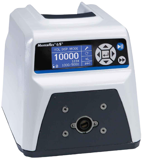
The Masterflex L/S® peristaltic pump is a versatile and reliable pump designed for fluid handling applications. It offers precise control over flow rates and is commonly used in laboratory and industrial settings. This readme provides important information and instructions for setting up and operating the Masterflex L/S® pump with the Aqueduct system.
Specifications
| Feature | Value |
|---|---|
| Pump Series | L/S |
| Control Type | Digital Variable Speed |
| Min RPM (rpm) | 0.1 |
| Max RPM (rpm) | 600 |
| Speed | Variable |
| Speed Control | ±0.1% (0.1 rpm at 600 rpm) |
| Max Flow Rate (mL/min) | 3400 |
| Min Flow Rate (mL/min) | 0.006 |
| Directionality | Bi-directional (Reversible motor) |
For complete specifications, see Cole-Parmer's documentation here.
Setup and Connection
To connect the Masterflex L/S® peristaltic pump to the Aqueduct system, follow these steps:
- Connect the Cole-Parmer Masterflex L/S® peristaltic pump to the Aqueduct Masterflex L/S® Mixed Signal (4-20mA I/O, isolated DIO) Node using a straight-through, shielded DB-25 cable.
- Connect the Masterflex Device Node to an Aqueduct Hub using an Aqueduct CommCable.
Configuration
To properly interface with the Device Node, several configuration settings must be changed on the Masterflex L/S® peristaltic pump. Follow these steps:
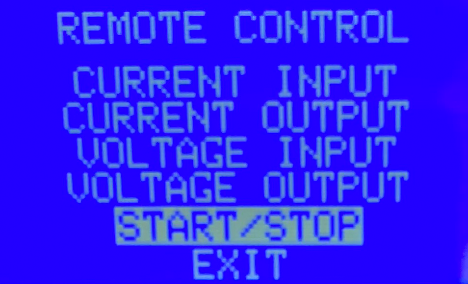
Remote Start/Stop
- With the Masterflex L/S® pump powered on, press the Enter button to view the Settings Menu.
- Use the Up and Down arrows to select START/STOP. Press Enter.
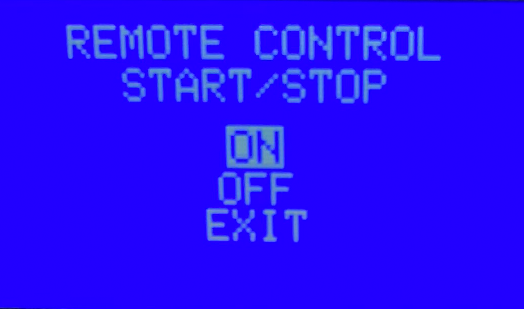
- Select ON. Press Enter.
|
|
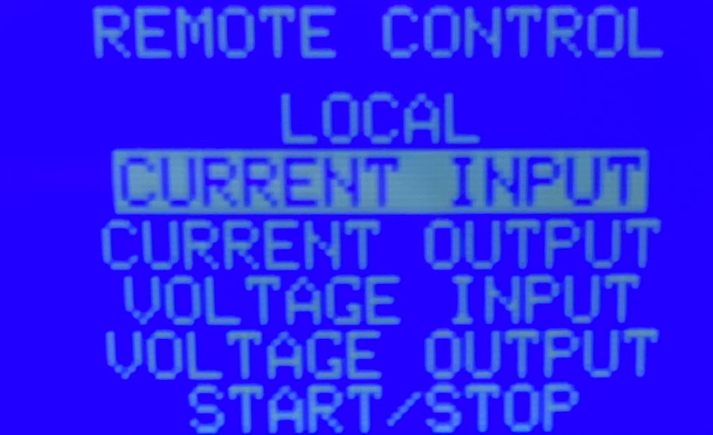
Update Current Input
- Return to the main Settings Menu. Use the Up and Down arrows to select CURRENT INPUT. Press Enter.
- Use the Up and Down arrows to set MIN. 4.2 mA = 0.0 mL/min. Press Enter.
- Use the Up and Down arrows to navigate to MAX.
- Assign your desired maximum flow rate to 19.7 mA. For instance, if you wish to achieve a maximum flow rate of 100 mL/min, set MAX. 19.7 mA = 100.0 mL/min. Press Enter.
|
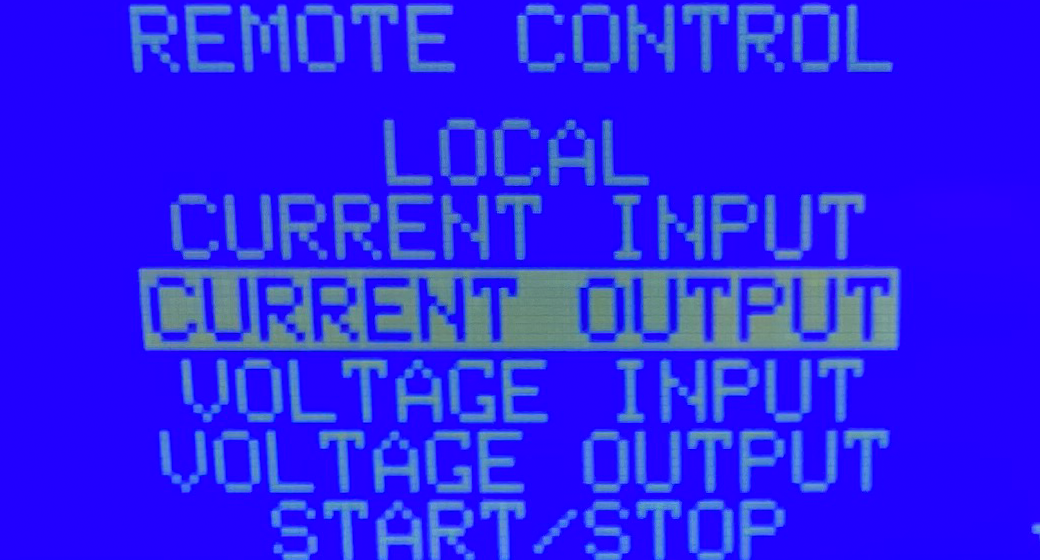
Update Current Output
- Return to the main Settings Menu. Use the Up and Down arrows to select CURRENT OUTPUT. Press Enter.
- Use the Up and Down arrows to set MIN. 4.2 mA = 0.0 mL/min. Press Enter.
- Use the Up and Down arrows to navigate to MAX.
- Assign your desired maximum flow rate to 19.7 mA. For instance, if you wish to achieve a maximum flow rate of 100 mL/min, set MAX. 19.7 mA = 100.0 mL/min. Press Enter.
|
Note: Use the same maximum flow rate that you used in the Current Input step.
Speed Control Calibration
The Aqueduct Device Node outputs an analog signal to control the speed of the Masterflex L/S® pump. Prior to operation, a calibration routine should be performed to ensure accurate scaling of the output signal.
Caution: This calibration protocol will automatically set the pump to run while calibrating. Please take into consideration that the pump may cause fluid flow.
Calibration Procedure
- Navigate to the Sandbox in Lab Mode and select the Masterflex L/S® peristaltic pump that you wish to calibrate.
- Right-click the name of the of the Masterflex L/S® peristaltic pump device in the Device Menu or the Sandbox Icon. Click:
Actions > Calibrate
- Follow the on-screen prompts. The system will automatically set a low flow rate. The user must enter the flow rate displayed on the Masterflex L/S® pump screen and click "Set" to save the low point calibration. Press continue to perform the high point calibration.
- The system will then automatically set a higher flow rate. The user must enter the second flow rate displayed on the Masterflex L/S® pump screen and click "Set" to save the high point calibration.
- The system will then automatically stop the pump, and the new calibration factor will be stored on the Aqueduct Masterflex Device Node.
Note: The Device Node stores the calibration factor for one specific pump. The Masterflex L/S® pump and Aqueduct Device Node should be treated as a matched pair until re-calibration is completed.