Tangential Flow Filtration
Table of Contents
- Tangential Flow Filtration
- Table of Contents
- Overview
- Success Story
- Control
- Hardware
- Try It Out
- Simulated Process Model Module
Overview
Tangential Flow Filtration (TFF) is a process used to separate or remove small solids from a feed liquid. A typical hardware setup for TFF consists of a:
-
Feed Pump: The feed pump is responsible for supplying the liquid feed to the TFF system. It provides the necessary pressure and flow rate to maintain the desired filtration conditions.
-
Tangential Flow Filter: The TFF filter is a key component that separates or removes small solids from the feed liquid. It consists of a membrane or porous material that allows the liquid to pass through while retaining the solids.
-
Permeate Pump: The permeate pump is used to collect the filtered liquid, known as permeate. It creates a pressure gradient that helps draw the permeate through the filter and into a collection container.
-
Buffer Pump: In some TFF setups, a buffer pump may be included in the hardware configuration. The buffer pump is responsible for supplying buffer solution or additional liquid to the TFF system. It helps maintain the desired volume and composition of the liquid within the system, ensuring optimal filtration conditions. The buffer pump can be controlled to adjust the flow rate and maintain a consistent buffer solution concentration throughout the process. Its integration enhances the control and stability of the TFF operation, especially when dealing with sensitive samples or complex filtration requirements.
-
Retentate Collector: The retentate collector receives the liquid that does not pass through the filter. It contains the retained solids or concentrated liquid and can be directed back to the feed tank for recirculation or further processing.
-
Flow Control Valves: Flow control valves, such as pinch valves or solenoid valves, are used to regulate the flow rates and control the direction of liquid within the TFF system.
-
Pressure Sensors: Pressure sensors are employed to monitor the pressure at different stages of the TFF system, including the feed, retentate, and permeate. These sensors provide real-time feedback on the system's performance and assist in controlling the filtration process.
-
Balance or Weighing System: In some TFF setups, a balance or weighing system may be included to measure the weight or mass of the liquid during the filtration process. This allows for precise monitoring and control of the filtration parameters, such as flow rates and mass accumulation.
Success Story
Background
A leading pharmaceutical company engaged Aqueduct to implement automation, control, and data logging to their TFF systems. The project aimed to provide user controls and capture process parameters to ensure consistency from operator to operator, enhancing efficiency and reproducibility in their operations.
Challenges
- Ensuring precise control and monitoring of pressures throughout the TFF process
- Integrating multiple hardware components into the system
- Validating and optimizing the process prior to physical implementation to minimize risks and costs
- Documentation and knowledge transfer to ensure long-term operability and maintenance of the system
Key Features:
-
Simulation-Based Process Refinement:
- Utilized the Aqueduct platform's simulated model to estimate pressures and monitor balance volume accumulation during the TFF process.
- Iteratively refined and optimized the process logic exclusively in the simulation mode, ensuring an understanding of the system's behavior and performance.
-
Hardware Integration:
- Integrated three Masterflex Peristaltic Pumps, an Aqueduct-designed pinch valve, three Ohaus Scout and Adventurer balances, and three Parker Scilog pressure transducers into the TFF system.
- Ensured communication between the hardware components and the Aqueduct platform for control, accurate measurements, and real-time feedback.
-
Initial Concentration, Diafiltration, and Ultrafiltration:
- Leveraged the Aqueduct platform's capabilities to perform initial concentration, diafiltration, and ultrafiltration steps within the TFF process.
- Ensured precise control and accurate monitoring of the concentration and volume exchange processes.
-
Centralized Data Logging:
- Building on top of the Aqueduct platform, implemented a central data logging platform to capture real time data from multiple systems and store process parameters in a centralized database.
Simulated Process Model Module
As part of the development process, Aqueduct implemented a process model to simulate inline pressures as a function of pump rates, pinch valve position, and filter parameters. Using the model, control logic for the pinch valve was refined and validated before running the process with real hardware. You can see the details of the pressure model here.
Additionally, the simulated process includes an optional error factor for the volume collection rate on the feed balance and the setpoint rate for the buffer pump. This error simulates tubing wear and was used to implement weight-driven control of the buffer pump instead of relying on the nominal setpoint to maintain a constant feed vessel weight.
Control
The TFF simulated model in the Aqueduct platform allowed for testing control algorithms for the TFF processes prior to applying them in the laboratory with real reagents and equipment.
Key control points for the TFF system include:
-
Feed Pump Rate: The TFF process model incorporates feed pump rate adjustment logic to ensure optimal performance. This logic dynamically adjusts the buffer pump rate based on the deviation between the actual weight accumulation on the balance and the target flow rate of the feed pump.
-
PID Control of Pinch Valve: The Aqueduct platform supports PID (Proportional-Integral-Derivative) control of the pinch valve to regulate the transmembrane pressure in the TFF system.
-
Target Permeate Collection Weight: The process also allows you to set a target permeate collection weight. By specifying the desired weight, the system can automatically adjust the TFF process parameters to achieve the desired volume of permeate collected.
Adjusting Feed Pump Rate
The TFF process model incorporates a feed pump rate adjustment logic to ensure optimal performance. This feature helps account for factors such as tubing wear and pump deviations from the setpoint, ensuring accurate measurements and precise control in the TFF process.
The adjustment logic focuses on monitoring the deviation between the actual weight accumulation on the balance and the target flow rate of the feed pump. By continuously comparing the accumulation rates of the scales with set thresholds, the model can make necessary adjustments to the feed pump rate.
The adjustment algorithm operates in two modes:
-
Mode 1: Δm/Δt Adjustment
- In this mode, the buffer pump rate is adjusted to force the rate of change (Δm/Δt) on the feed balance to zero. This helps maintain a stable product concentration and minimize fluctuations caused by variations in the feed pump rate.
-
Mode 2: Setpoint-driven Adjustment
- In this mode, the buffer pump rate is adjusted to drive the feed balance mass to a specific setpoint at a specified rate. This ensures that the weight accumulation on the balance aligns with the desired setpoint, enabling accurate control of the TFF process.
The adjustment algorithm takes into account parameters such as maximum deviation thresholds, maximum pump adjustment limits, and target mass or time to reach the setpoint. By dynamically modifying the pump rates within the specified limits, the model compensates for tubing wear, pump deviations, and other factors that may affect the balance readings.
While the feed pump adjustment logic is specifically designed for the real application of the TFF process, it is important to note that the logic can be tested and validated in the simulation mode. By configuring the simulated balance instrument to deviate from the pump's target flow rate, the model's performance can be assessed and fine-tuned to ensure accurate measurements and precise control.
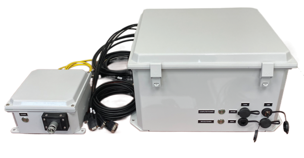
Hardware
The delivered TFF system was comprised of two enclosures.
The Main Enclosure (pictured right) serves as the central hub of the TFF System. It houses a computer that runs the Aqueduct software application and is equipped with 5 Device Nodes. These Device Nodes provide the interface for connecting and controlling the various components. In the default configuration, the Device Nodes facilitate communication with 3 Masterflex L/S Peristaltic Pumps, 3 Ohaus Adventurer balances, and 3 Parker SciLog pressure transducers. However, we can incorporate different models or brands of pumps, pressure transducers, or balances as needed.
The Pinch Valve Enclosure (pictured left) accommodates a Pinch Valve and the necessary driver electronics. It can be positioned close to the process and is connected to the Main Enclosure with a dedicated power and communications cable.
|
Try It Out
To run the TFF recipe locally in simulation mode:
-
Install the Aqueduct application.
-
Download the Aqueduct examples repository and extract the compressed archive.
-
Navigate to the Library page and upload the
/apps/filtration/tffdirectory from the extracted archive. -
Navigate to the Dashboard page and upload the necessary .recipe, .setup, and .layout files found in the
/apps/filtration/modelsdirectory. -
Activate the
TFF - Full operationrecipe from your Dashboard and navigate to the Sandbox to view the simulated process.